


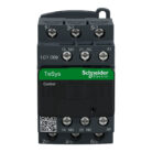

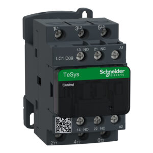
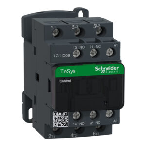
Schneider TeSys D contactor, 3P(3 NO), AC-3, <= 440 V 9 A, 110 VAC Coil
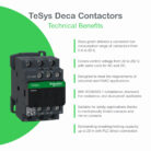
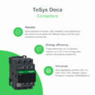
TeSys D contactor, 3 poles (3NO), for motor control applications up to 9A/690V AC-3/3e (4kW@400V). It provides a 110V 50/60Hz AC coil, 1NO+1NC built-in auxiliary contacts (NC mirror certified), and connection by screw clamp terminals. For operating rates until 3600 cycles/hour and environments until 60°C, it procures high reliability and durability to demanding applications. Compact (45mm width), DIN-rail mounting or screw fixing. Multi standards certified (IEC, UL, CSA, CCC, EAC, Marine), Green Premium compliant (RoHS/REACh).
- New modern look & feel of all machines
- Easier to install and operate with multi-standard screws
- Improved fire resistance with IEC 60335-1(Clause 30.2) certificate by authorised agency
- Anti-flammable refrigerants with IEC/EN/UL 60335-2-40(Annexe JJ) certificate by an authorised agency
- Digital customer experience for technical documents
Environmental Data Explained
How We Assess Product Sustainability
LC1D09F7, TeSys D contactor, 3P(3 NO), AC-3, <= 440 V 9 A, 110 VAC coil
TeSys D contactor, 3 poles (3NO), for motor control applications up to 9A/690V AC-3/3e (4kW@400V). It provides a 110V 50/60Hz AC coil, 1NO+1NC built-in auxiliary contacts (NC mirror certified), and connection by screw clamp terminals. For operating rates until 3600 cycles/hour and environments until 60°C, it procures high reliability and durability to demanding applications. Compact (45mm width), DIN-rail mounting or screw fixing. Multi standards certified (IEC, UL, CSA, CCC, EAC, Marine), Green Premium compliant (RoHS/REACh).
SPECIFICATIONS
| Range of product | TeSys Deca |
|---|---|
| Product or component type | Contactor |
| Device short name | LC1D |
| Contactor application | Resistive load Motor control |
| Utilisation category | AC-1 AC-3 AC-4 AC-3e |
| Poles description | 3P |
| [Ue] rated operational voltage | Power circuit: <= 690 V AC 25…400 Hz Power circuit: <= 300 V DC |
| [Ie] rated operational current | 9 A (at <60 °C) at <= 440 V AC AC-3 for power circuit 25 A (at <60 °C) at <= 440 V AC AC-1 for power circuit 9 A (at <60 °C) at <= 440 V AC AC-3e for power circuit |
| [Uc] control circuit voltage | 110 V AC 50/60 Hz |
| Motor power kW | 2.2 kW at 220…230 V AC 50/60 Hz (AC-3) 4 kW at 380…400 V AC 50/60 Hz (AC-3) 4 kW at 415…440 V AC 50/60 Hz (AC-3) 5.5 kW at 500 V AC 50/60 Hz (AC-3) 5.5 kW at 660…690 V AC 50/60 Hz (AC-3) 2.2 kW at 400 V AC 50/60 Hz (AC-4) 2.2 kW at 220…230 V AC 50/60 Hz (AC-3e) 4 kW at 380…400 V AC 50/60 Hz (AC-3e) 4 kW at 415…440 V AC 50/60 Hz (AC-3e) 5.5 kW at 500 V AC 50/60 Hz (AC-3e) 5.5 kW at 660…690 V AC 50/60 Hz (AC-3e) |
|---|---|
| Motor power hp | 1 hp at 230/240 V AC 50/60 Hz for 1 phase motors 2 hp at 200/208 V AC 50/60 Hz for 3 phases motors 2 hp at 230/240 V AC 50/60 Hz for 3 phases motors 5 hp at 460/480 V AC 50/60 Hz for 3 phases motors 7.5 hp at 575/600 V AC 50/60 Hz for 3 phases motors 0.33 hp at 115 V AC 50/60 Hz for 1 phase motors |
| Compatibility code | LC1D |
| Pole contact composition | 3 NO |
| Protective cover | With |
| [Ith] conventional free air thermal current | 25 A (at 60 °C) for power circuit 10 A (at 60 °C) for signalling circuit |
| Irms rated making capacity | 250 A at 440 V for power circuit conforming to IEC 60947 140 A AC for signalling circuit conforming to IEC 60947-5-1 250 A DC for signalling circuit conforming to IEC 60947-5-1 |
| Rated breaking capacity | 250 A at 440 V for power circuit conforming to IEC 60947 |
| [Icw] rated short-time withstand current | 105 A 40 °C – 10 s for power circuit 210 A 40 °C – 1 s for power circuit 30 A 40 °C – 10 min for power circuit 61 A 40 °C – 1 min for power circuit 100 A – 1 s for signalling circuit 120 A – 500 ms for signalling circuit 140 A – 100 ms for signalling circuit |
| Associated fuse rating | 10 A gG for signalling circuit conforming to IEC 60947-5-1 25 A gG at <= 690 V coordination type 1 for power circuit 20 A gG at <= 690 V coordination type 2 for power circuit |
| Average impedance | 2.5 mOhm – Ith 25 A 50 Hz for power circuit |
| Power dissipation per pole | 1.56 W AC-1 0.2 W AC-3 0.2 W AC-3e |
| [Ui] rated insulation voltage | Power circuit: 690 V conforming to IEC 60947-4-1 Power circuit: 600 V CSA certified Power circuit: 600 V UL certified Signalling circuit: 690 V conforming to IEC 60947-1 Signalling circuit: 600 V CSA certified Signalling circuit: 600 V UL certified |
| Overvoltage category | III |
| Pollution degree | 3 |
| [Uimp] rated impulse withstand voltage | 6 kV conforming to IEC 60947 |
| Safety reliability level | B10d = 1369863 cycles contactor with nominal load conforming to EN/ISO 13849-1 B10d = 20000000 cycles contactor with mechanical load conforming to EN/ISO 13849-1 |
| Mechanical durability | 15 Mcycles |
| Electrical durability | 0.6 Mcycles 25 A AC-1 at Ue <= 440 V 2 Mcycles 9 A AC-3 at Ue <= 440 V 2 Mcycles 9 A AC-3e at Ue <= 440 V |
| Control circuit type | AC at 50/60 Hz standard |
| Coil technology | Without built-in suppressor module |
| Control circuit voltage limits | 0.3…0.6 Uc (-40…70 °C):drop-out AC 50/60 Hz 0.8…1.1 Uc (-40…60 °C):operational AC 50 Hz 0.85…1.1 Uc (-40…60 °C):operational AC 60 Hz 1…1.1 Uc (60…70 °C):operational AC 50/60 Hz |
| Inrush power in VA | 70 VA 60 Hz cos phi 0.75 (at 20 °C) 70 VA 50 Hz cos phi 0.75 (at 20 °C) |
| Hold-in power consumption in VA | 7.5 VA 60 Hz cos phi 0.3 (at 20 °C) 7 VA 50 Hz cos phi 0.3 (at 20 °C) |
| Heat dissipation | 2…3 W at 50/60 Hz |
| Operating time | 12…22 ms closing 4…19 ms opening |
| Maximum operating rate | 3600 cyc/h at 60 °C |
| Connections – terminals | Power circuit: screw clamp terminals 1 1…4 mm² – cable stiffness: flexible without cable end Power circuit: screw clamp terminals 2 1…4 mm² – cable stiffness: flexible without cable end Power circuit: screw clamp terminals 1 1…4 mm² – cable stiffness: flexible with cable end Power circuit: screw clamp terminals 2 1…2.5 mm² – cable stiffness: flexible with cable end Power circuit: screw clamp terminals 1 1…4 mm² – cable stiffness: solid without cable end Power circuit: screw clamp terminals 2 1…4 mm² – cable stiffness: solid without cable end Control circuit: screw clamp terminals 1 1…4 mm² – cable stiffness: flexible without cable end Control circuit: screw clamp terminals 2 1…4 mm² – cable stiffness: flexible without cable end Control circuit: screw clamp terminals 1 1…4 mm² – cable stiffness: flexible with cable end Control circuit: screw clamp terminals 2 1…2.5 mm² – cable stiffness: flexible with cable end Control circuit: screw clamp terminals 1 1…4 mm² – cable stiffness: solid without cable end Control circuit: screw clamp terminals 2 1…4 mm² – cable stiffness: solid without cable end |
| Tightening torque | Power circuit: 1.7 N.m – on screw clamp terminals – with screwdriver flat Ø 6 mm Power circuit: 1.7 N.m – on screw clamp terminals – with screwdriver Philips No 2 Control circuit: 1.7 N.m – on screw clamp terminals – with screwdriver flat Ø 6 mm Control circuit: 1.7 N.m – on screw clamp terminals – with screwdriver Philips No 2 Control circuit: 1.7 N.m – on screw clamp terminals – with screwdriver pozidriv No 2 Power circuit: 1.7 N.m – on screw clamp terminals – with screwdriver pozidriv No 2 |
| Auxiliary contact composition | 1 NO + 1 NC |
| Auxiliary contacts type | type mechanically linked 1 NO + 1 NC conforming to IEC 60947-5-1 type mirror contact 1 NC conforming to IEC 60947-4-1 |
| Signalling circuit frequency | 25…400 Hz |
| Minimum switching voltage | 17 V for signalling circuit |
| Minimum switching current | 5 mA for signalling circuit |
| Insulation resistance | > 10 MOhm for signalling circuit |
| Non-overlap time | 1.5 ms on de-energisation between NC and NO contact 1.5 ms on energisation between NC and NO contact |
| Mounting support | Plate Rail |
| Standards | CSA C22.2 No 14 EN 60947-4-1 EN 60947-5-1 IEC 60947-4-1 IEC 60947-5-1 UL 60947-4-1 IEC 60335-1:Clause 30.2 IEC 60335-2-40:Annex JJ UL 60335-2-40:Annex JJ CSA C22.2 No 60947-4-1 |
|---|---|
| Product certifications | UL CCC CSA Marine UKCA EAC CB Scheme |
| IP degree of protection | IP20 front face conforming to IEC 60529 |
| Protective treatment | TH conforming to IEC 60068-2-30 |
| Climatic withstand | conforming to IACS E10 exposure to damp heat conforming to IEC 60947-1 Annex Q category D exposure to damp heat |
| Permissible ambient air temperature around the device | -40…60 °C 60…70 °C with derating |
| Operating altitude | 0…3000 m |
| Fire resistance | 850 °C conforming to IEC 60695-2-1 |
| Flame retardance | V1 conforming to UL 94 |
| Mechanical robustness | Vibrations contactor open (2 Gn, 5…300 Hz) Vibrations contactor closed (4 Gn, 5…300 Hz) Shocks contactor open (10 Gn for 11 ms) Shocks contactor closed (15 Gn for 11 ms) |
| Height | 77 mm |
| Width | 45 mm |
| Depth | 86 mm |
| Net weight | 0.32 kg |
| Unit Type of Package 1 | PCE |
|---|---|
| Number of Units in Package 1 | 1 |
| Package 1 Height | 5.000 cm |
| Package 1 Width | 9.200 cm |
| Package 1 Length | 11.200 cm |
| Package 1 Weight | 353.000 g |
| Unit Type of Package 2 | S02 |
| Number of Units in Package 2 | 20 |
| Package 2 Height | 15.000 cm |
| Package 2 Width | 30.000 cm |
| Package 2 Length | 40.000 cm |
| Package 2 Weight | 7.390 kg |
| Warranty | 18 months |
|---|
Visit our website to: Request for Quote Form – Emobella Engineering
| Weight | 0.32 kg |
|---|---|
| Dimensions | 8.60 × 4.50 × 7.70 cm |
Be the first to review “Schneider TeSys D contactor, 3P(3 NO), AC-3, <= 440 V 9 A, 110 VAC Coil”
Shipping policy
At our Company, we understand the importance of timely delivery. We offer a variety of shipping options to suit your needs, including standard, expedited, and express shipping. Our dedicated team works diligently to process and dispatch your orders promptly, aiming to deliver them to your doorstep within the estimated timeframe.
We strive to provide fast and reliable shipping to our customers. Here’s everything you need to know about our shipping process:
- Dispatch: Within 24 Hours
- Free shipping across all products on a minimum purchase of $99.
- International delivery time 5 to 7 business days
- Cash on delivery might be available
- Easy 30 days returns and exchanges
Please note that delivery times are estimates and may vary depending on factors such as product availability, destination, and carrier delay
Returns policy
We want you to be completely satisfied with your purchase from our website. If for any reason you are not entirely happy with your order, we’re here to help. Certain exclusions and conditions may apply, so we encourage you to review our detailed return policy for more information. Rest assured, our goal is to ensure your complete satisfaction with every purchase you make from our website
- Returned items must be unused, undamaged, and in the same condition as received.
- Original tags, labels, and packaging must be intact and included with the returned item.
- Proof of purchase, such as your order confirmation or receipt, is required for all returns.


Reviews
There are no reviews yet.